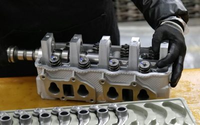
If you’ve ever looked at a perfectly dimensioned part on a drawing and assumed production would reproduce it exactly, the first run off a CNC machine usually corrects that assumption fast.
No machined part is ever truly identical to its CAD model or drawing. Every component carries a small, controlled amount of dimensional variation — driven by machine dynamics, tool wear, material behavior, fixturing, and even ambient shop temperature. The role of CNC machining tolerances isn’t to eliminate this variation. It’s to define exactly how much deviation a part can carry and still function correctly within an assembly.
In practical manufacturing terms, tolerancing is the point where design intent meets real-world production capability. It’s the bridge between a CAD model and a part that actually fits, seals, rotates, or locates the way the design engineer intended.
In this guide, we’ll break down CNC machining tolerances as they’re actually understood on the shop floor — what’s realistically achievable across different processes, which variables influence dimensional accuracy and repeatability, how tolerance selection affects machining costs, and how design engineers can specify tolerances without creating avoidable manufacturing bottlenecks.
What Are CNC Machining Tolerances?
Understanding the Concept in Practical Manufacturing Terms
A machining tolerance is the allowable dimensional variation from a specified nominal value. It’s the engineering definition of “close enough to work.”
Consider a simple example. If a drawing calls out a shaft diameter as:
25.00 mm ± 0.05 mm
this doesn’t mean every shaft produced will measure exactly 25.00 mm. It means any shaft falling between:
- 24.95 mm (lower limit)
- 25.05 mm (upper limit)
is dimensionally acceptable and fit for use.
From a production standpoint, tolerances aren’t about chasing perfection — they’re about defining a safe, repeatable operating window for dimensional control, fit, and function.
Why Tolerances Exist in the First Place
Even the most advanced CNC machining centers cannot eliminate dimensional variation entirely. The reasons are rooted in real, physical manufacturing conditions:
- Cutting tools wear gradually with each pass, altering chip load and surface generation
- Materials expand and contract with temperature fluctuations and internal stress relief
- Machine structures experience microscopic vibration, deflection, and chatter under cutting load
- Workholding and fixtures introduce slight repeatability and positional variation
- Operator setup, tool offsets, and probing routines introduce small process inconsistencies
So rather than chasing impossible zero-variation parts, manufacturing engineers define acceptable dimensional limits — tolerance bands — that still guarantee fit, function, and reliability in the field.
Accuracy vs. Precision in CNC Machining
These two terms get used interchangeably outside the shop floor, but in manufacturing engineering they describe two completely different process behaviors.
| Term | Meaning in Practice |
|---|---|
| Accuracy | How close a measured dimension is to the intended (true) value |
| Precision | How consistent and repeatable dimensions are across multiple parts |
A Real Example from Production
If we run a production batch of 100 shafts on a CNC lathe:
- If all 100 shafts measure between 24.999–25.001 mm → the process shows high precision (tight repeatability)
- If the average of those measurements also sits close to 25.000 mm → the process also shows high accuracy
A capable CNC process needs both accuracy and precision simultaneously. A machine that produces highly consistent parts that are consistently off-target is just generating repeatable scrap — and that’s a process control problem, not a tolerancing problem.
Standard CNC Machining Tolerances (Realistic Shop Floor Ranges)
The tolerance a given process can hold depends heavily on machining method, material machinability, tooling condition, and setup rigidity. Below are practical, field-tested tolerance ranges — not theoretical machine specifications.
| Process | Practical Achievable Tolerance |
|---|---|
| CNC Milling | ±0.02 to ±0.05 mm |
| CNC Turning | ±0.01 to ±0.03 mm |
| Surface Grinding | ±0.002 to ±0.005 mm |
| Cylindrical Grinding | ±0.001 to ±0.003 mm |
| Wire EDM | ±0.002 mm or better |
| Honing | ±0.001 mm (under controlled conditions) |
These figures reflect what is consistently achievable in stable, well-maintained production environments — not best-case lab results.
CNC Machining Tolerance Chart (Quick Engineering Reference)
This is the general tolerance guidance most design engineers default to during early-stage drafting, before applying tighter callouts where function demands it:
| Nominal Size Range | General Machining Tolerance |
|---|---|
| 0 – 6 mm | ±0.05 mm |
| 6 – 30 mm | ±0.10 mm |
| 30 – 120 mm | ±0.15 mm |
| 120 – 400 mm | ±0.20 mm |
| 400 mm and above | Depends on geometry, process, and fixturing |
As a general design rule: specify tighter tolerances only on features where function, fit, or sealing actually demands it. Blanket tight tolerancing across a drawing inflates cost without improving part performance.
Types of CNC Machining Tolerances
Linear (Dimensional) Tolerances — The Most Common
These govern the basic dimensions that appear on nearly every engineering drawing:
- Diameter
- Length
- Thickness
- Depth
This is the foundation layer of dimensional control, and it’s where most tolerance conversations start — but it’s rarely where the real engineering risk lives.
Geometric Tolerances (GD&T) — Where Most Design Misunderstandings Happen
Geometric Dimensioning and Tolerancing (GD&T) controls form, orientation, and location — not just size. This is where the majority of fit and assembly issues actually originate.
| Geometric Control | What It Governs |
|---|---|
| Flatness | Surface evenness across a single plane |
| Parallelism | Alignment between two surfaces or axes |
| Perpendicularity | 90° relationship between features |
| Circularity (Roundness) | Roundness consistency of a cylindrical feature |
| Concentricity | Shared centerline alignment between features |
| Position (True Position) | Precise location of a feature relative to a datum |
Geometric tolerances matter far more than most designers initially assume — particularly in rotating assemblies, bearing fits, and hydraulic components, where misalignment translates directly into vibration, leakage, or premature wear.
Angular Tolerances
Angular tolerances define how accurately two surfaces or features meet at a specified angle. They’re common in:
- Machined fixtures and jigs
- Structural brackets
- Valve bodies and hydraulic manifolds
- Multi-axis mechanical assemblies
Even small angular deviations can compound into significant misalignment once parts are stacked into an assembly — a phenomenon known in dimensional engineering as tolerance stack-up.
Surface Finish (Often Overlooked, But Functionally Critical)
Surface finish (commonly specified as Ra, the arithmetic average roughness) is frequently treated as cosmetic. In reality, it directly governs sealing performance, friction, fatigue life, and wear behavior.
| Ra Value | Typical Application |
|---|---|
| 3.2 µm | General machining, non-critical surfaces |
| 1.6 µm | Functional machined parts, standard fits |
| 0.8 µm | Sealing surfaces, hydraulic applications |
| 0.4 µm | Precision engineering components, bearing seats |
| 0.2 µm | Ultra-critical surfaces, dynamic sealing interfaces |
In hydraulic and pneumatic systems specifically, surface finish has a direct, measurable influence on leakage rates, seal wear, and long-term operational reliability.
What Actually Affects CNC Machining Tolerances
From a process-engineering standpoint, achievable tolerance is never a single number pulled from a spec sheet — it’s the result of several interacting variables.
Machine Condition
A CNC machine is only as accurate as its current mechanical and thermal condition. Key factors include:
- Spindle health and runout
- Axis backlash and ball-screw wear
- Thermal stability and warm-up behavior
- Calibration and compensation status
- Overall machine rigidity and structural damping
Even a high-end machining center will produce inconsistent, out-of-tolerance parts if preventive maintenance and calibration are neglected.
Material Behavior and Machinability
Different engineering materials respond very differently under cutting loads, heat generation, and residual stress relief.
| Material | Dimensional Stability During Machining |
|---|---|
| Aluminum | Very stable, excellent machinability |
| Brass | Stable, free-machining |
| Mild Steel | Good, predictable behavior |
| Stainless Steel | Medium — prone to work hardening |
| Titanium | Difficult — heat buildup and tool deflection |
Material movement after machining — from residual stress release or thermal relaxation — is also a major factor, especially in long, thin, or asymmetric components.
Tool Wear and Deflection
This is one of the most persistent real-world challenges in holding tight tolerances over a production run. As cutting tools wear:
- Dimensions gradually drift out of the target window
- Surface finish quality deteriorates
- Cutting heat increases
- Cutting forces and tool deflection change
Proactive tool life management and wear monitoring are essential whenever tight-tolerance work is involved.
Part Design Geometry
Some part geometries are inherently harder to hold in tolerance, regardless of machine quality:
- Thin-walled sections
- Deep cavities and pockets
- Long, slender shafts
- Small-diameter features and fine details
These geometries amplify vibration, chatter, and deflection during cutting, making dimensional control significantly more challenging.
Temperature and Environmental Control
This variable is frequently underestimated outside precision manufacturing. A 10°C ambient temperature shift can move dimensions at the micron level in precision work — which is exactly why CMM inspection rooms and precision grinding areas are typically climate-controlled.
Tight Tolerance Machining Explained
“Tight tolerance” simply means reducing the allowable dimensional variation to a very narrow band.
| Category | Typical Tolerance |
|---|---|
| Standard machining | ±0.05 mm |
| Precision machining | ±0.02 mm |
| High precision | ±0.01 mm |
| Tight tolerance | ±0.005 mm |
| Ultra precision | ±0.002 mm or tighter |
Tighter, however, is not automatically better. Every reduction in tolerance band increases:
- Machining cycle time
- Inspection frequency and documentation load
- Rejection and rework risk
- Overall production cost
How Tight Can CNC Machining Realistically Go?
Under controlled, well-engineered process conditions, these limits are realistically achievable:
| Process | Achievable Limit |
|---|---|
| CNC Turning | ±0.005 to ±0.01 mm |
| CNC Milling | ±0.01 mm |
| Grinding | ±0.002 mm |
| Wire EDM | ±0.002 mm |
| Honing | ±0.001 mm |
Achieving these numbers consistently across a production batch requires disciplined process planning, fixture design, and inspection routines — not just a capable machine on the shop floor.
CNC Tolerances by Industry
Automotive Manufacturing
Automotive components typically balance dimensional performance against per-unit cost at high volumes. Critical tolerance zones include:
- Engine systems and valve trains
- Fuel delivery and injection components
- Transmission and drivetrain components
Over-specifying tolerances on non-critical automotive features remains one of the most common and costly design mistakes in this sector.
Aerospace Components
In aerospace machining, tolerances are driven primarily by:
- Flight safety margins
- Certification and traceability requirements
- High-stress, high-cycle-fatigue operating environments
Even small dimensional deviations here can meaningfully affect structural performance, which is why aerospace parts typically demand full CMM-based dimensional verification.
Hydraulic Systems
Hydraulic components are extremely sensitive to clearance control between mating parts. If tolerances are specified too loose, internal leakage and pressure loss occur. If tolerances are too tight, friction increases and wear accelerates prematurely. Hydraulic tolerancing is fundamentally a balance between sealing performance and free movement — getting this wrong in either direction degrades system efficiency.
Medical Devices
Medical components typically require:
- High dimensional precision
- Strong part-to-part repeatability
- Biocompatibility-driven material and surface constraints
Inspection and documentation standards in this sector are correspondingly strict, often requiring full dimensional reports per batch.
The Real Cost of Tight Tolerances
This is where many otherwise well-engineered designs run into avoidable cost issues. As tolerances tighten:
- Cycle times increase due to slower feeds and finishing passes
- Machines require reduced feed rates to control deflection and chatter
- Additional setups or secondary operations (grinding, honing, EDM) may be needed
- Inspection frequency and CMM time increase
- Scrap and rework rates rise
Cost Impact — A Practical View
| Tolerance Level | Relative Cost Impact |
|---|---|
| ±0.10 mm | Baseline |
| ±0.05 mm | ~1.3x |
| ±0.02 mm | ~1.8x |
| ±0.01 mm | ~2.5x |
| ±0.005 mm | ~3.5x – 5x |
The engineering question that should drive every tolerance callout is simple: does this dimension actually need this level of precision to function correctly? If the answer is no, loosening it is free cost savings with zero functional downside.
Common Engineering Mistakes in Tolerance Specification
Over-tolerancing non-critical features This is, by far, the most frequent issue seen in incoming production drawings — tight tolerances applied uniformly across a part instead of targeted at functional features.
Ignoring material behavior Materials move, relax, and distort after machining. Designs and tolerance allowances should account for this rather than assuming as-machined dimensions are final.
Assuming CNC machines eliminate variation CNC processes reduce and control variation — they do not eliminate it. Every process has an inherent capability window.
Poor or inconsistent GD&T usage Incorrect or ambiguous GD&T callouts create confusion on the shop floor, inconsistent interpretation between inspectors, and avoidable manufacturing delays.
 How Tolerances Are Measured in Real Manufacturing
 How Tolerances Are Measured in Real Manufacturing
Basic Measuring Tools
- Vernier calipers — general dimensional checks
- Micrometers — high-accuracy diameter and thickness checks
- Bore gauges — internal diameter verification
- Coordinate Measuring Machine (CMM) — used when precision and full traceability matter
CMM inspection enables:
- Full 3D dimensional measurement
- Complex geometry and GD&T verification
- Repeatable, documented inspection reports
CMM-based verification is standard practice in aerospace, medical, and high-precision manufacturing environments where dimensional traceability is a contractual or regulatory requirement.
How We Approach Tolerances at Attri Tech Machines
From a manufacturing standpoint, the goal isn’t simply to “meet tolerance” on a single part — it’s to consistently control dimensional variation across every batch, every run, every order.
In our CNC machining processes, we focus on:
- Stable, calibrated machining conditions across all equipment
- Controlled tool wear monitoring throughout production runs
- In-process inspection routines to catch drift before it becomes scrap
- Final CMM verification for critical, function-driven components
- Process validation and first-article inspection before mass production
Over time, it’s this process-driven discipline — not isolated part-by-part luck — that ensures dimensional consistency across batches, machines, and production runs.
Frequently Asked Questions
What is the standard CNC machining tolerance?
For general-purpose CNC machining, the commonly applied tolerance is around ±0.025 mm (roughly ±0.001″), though this isn’t a fixed rule — it shifts based on the process used, the feature’s nominal size, and the material being cut. A 5 mm pin and a 200 mm housing bore won’t realistically hold the same absolute tolerance, even on the same machine. Most shops default to ISO 2768 medium-class tolerances unless the drawing specifies something tighter, since this range is achievable on a well-maintained 3-axis mill or lathe without special process controls.
What is considered tight tolerance machining?
Tight tolerance generally starts at ±0.005 mm (5 microns) or tighter. Below this threshold, standard milling and turning processes alone usually can’t hold the dimension reliably across a full production run — secondary operations like grinding, honing, or wire EDM typically become necessary. Tight tolerance work also demands stricter environmental control (climate-controlled inspection areas), more frequent in-process measurement, and tighter fixturing to eliminate part movement during cutting.
Why do tight tolerances increase machining cost?
Tighter tolerances drive cost up through several compounding factors: slower feeds and speeds to reduce tool deflection and vibration, additional finishing passes or secondary processes (grinding, honing, EDM), more frequent in-process and final inspection, longer CMM cycle times, and higher rejection/rework rates when a process drifts even slightly out of band. None of these costs scale linearly — moving from ±0.01 mm to ±0.005 mm often more than doubles per-part cost, because the process now has far less margin for normal machine and material variation.
What is the difference between tolerance and accuracy?
Accuracy describes how close a measured dimension sits to the intended target value — essentially, how “correct” the part is. Tolerance is the engineered allowance, the defined window of acceptable deviation around that target. A part can be accurate (right on target) without needing a tight tolerance, and a process can hold a tight tolerance band while still being inaccurate if it’s consistently biased off-center. In short: accuracy is about correctness, tolerance is about the permitted range of error.
Can all CNC machines achieve tight tolerances?
No. Tolerance capability isn’t just a function of the machine’s published spec sheet — it depends on spindle condition, axis backlash, thermal stability, fixture rigidity, material machinability, and the surrounding environment. A high-end 5-axis machining center that’s poorly maintained or running in an uncontrolled temperature environment can underperform a properly calibrated, well-maintained mid-range machine. Tight tolerance capability is a property of the whole process — machine, tooling, fixturing, material, and environment together — not the machine alone.
How is the correct tolerance determined for a given part feature?
Tolerance selection should be function-driven, not arbitrary. Engineers typically start by asking what role the feature plays: Is it a sealing surface? A bearing fit? A non-critical clearance hole? Features involved in fits, sealing, alignment, or load transfer need tolerances tight enough to guarantee that function across the full range of mating parts (often calculated through tolerance stack-up analysis). Cosmetic or non-mating features can usually default to standard shop tolerances. A useful rule: tolerance to the loosest value that still guarantees the part performs correctly in every assembly condition — not the tightest value that “feels safe.”
What is GD&T, and why does it matter more than basic dimensional tolerances?
GD&T (Geometric Dimensioning and Tolerancing) is a standardized symbolic language used to define form, orientation, location, and runout — not just size. Two parts can be perfectly within their linear dimensional tolerances and still fail to assemble correctly if flatness, perpendicularity, or true position aren’t controlled. GD&T matters because most real-world fit and function failures trace back to geometric relationships, not raw size error. Clear, correctly applied GD&T also reduces ambiguity between design intent and shop-floor interpretation, which cuts down on inspection disputes and rework.
Does tolerance requirement change between prototype and production runs?
Often, yes — though the part’s functional tolerance shouldn’t change just because volume does. What does change is how that tolerance gets held economically. A single prototype part can justify a slower, more conservative machining strategy or an extra grinding pass to guarantee tolerance on one piece. At production volume, the same tolerance needs to be achievable repeatably and economically across hundreds or thousands of parts, which often pushes design and process teams toward better fixturing, tool life management, or statistical process control (SPC) rather than just “machining slower.”
How does tolerance stack-up affect assembly fit?
Tolerance stack-up occurs when the individual tolerances of multiple mating parts combine within an assembly, potentially adding up to a total variation much larger than any single part’s tolerance. For example, three parts each within ±0.05 mm could combine for a worst-case stack-up of ±0.15 mm at the final assembly interface. Ignoring stack-up is a common source of assembly-line fit problems even when every individual part “passes” inspection. Engineers manage this through stack-up analysis (worst-case or statistical/RSS methods) during the design phase, allocating tolerance budgets across components rather than tightening every part uniformly.
What inspection method should be used to verify CNC machining tolerances?
The right inspection method depends on the tolerance band and feature type. General dimensions are typically checked with calipers or micrometers; internal diameters use bore gauges or pin gauges; complex geometry, GD&T callouts, and tight-tolerance features generally require a Coordinate Measuring Machine (CMM) for full 3D verification and a traceable inspection report. As a practical guideline: if a feature’s tolerance is tighter than what a micrometer can reliably resolve and repeat (generally below ±0.01 mm), CMM or comparable precision metrology becomes necessary rather than optional.
Conclusion
CNC machining tolerances are not just numbers printed on a drawing — they define how a part actually behaves in a real assembly, under real loads, in the field.
Good engineering isn’t about specifying everything as tight as possible. It’s about understanding precisely where dimensional precision matters functionally — and where it doesn’t. When tolerances are defined correctly, parts become easier to manufacture, more cost-effective to produce at scale, and more reliable in real-world operating conditions.
That balance — between functional precision and manufacturability — is what separates a good design from a truly manufacturable one.
Mr. Kuldeep Attri is the Founder and Director of Attri Tech Machines Pvt. Ltd., a precision engineering company specializing in CNC-machined components, throttle shafts, hydraulic valve components, carbide parts, pneumatic connectors, and custom-engineered industrial solutions. He founded the company in 2005 with the vision of building a manufacturing organization focused on precision, quality, reliability, and long-term customer partnerships.
With more than two decades of experience in precision manufacturing and industrial engineering, Mr. Attri has led the company's growth from a small manufacturing operation into an ISO 9001:2015-certified organization serving automotive, aerospace, government, engineering, hydraulics, and industrial sectors across India and international markets.
Under his leadership, Attri Tech Machines has developed advanced manufacturing capabilities including CNC turning, VMC machining, wire-cut EDM, sheet metal fabrication, tool and die manufacturing, and custom precision component production. The company operates a modern manufacturing facility in Ghaziabad, Uttar Pradesh, equipped to deliver high-precision components with stringent quality standards and on-time delivery commitments.
Mr. Attri regularly shares insights on:
CNC Machining & Manufacturing Processes
Precision Engineering
Automotive Components Manufacturing
Aerospace Machining Applications
Hydraulic Valve Components
Carbide Components & Tooling
Quality Control & ISO Manufacturing Standards
Industrial Product Development
Custom Component Manufacturing
Supply Chain & Production Excellence
His content combines practical manufacturing experience with real-world production insights, helping engineers, procurement teams, OEMs, and industrial businesses make informed decisions about precision component design and manufacturing.